AutoCAD Plant 3D Toolset | 3D Plant Design Layout ...
Create and edit PID''s, 3D models, and extract piping orthographics and isometrics with the comprehensive AutoCAD Plant 3D design and layout toolset.

 WhatsApp)
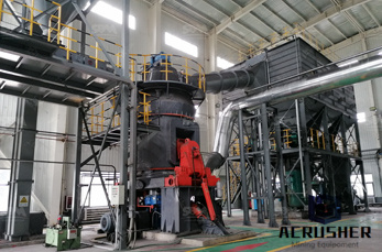
Create and edit PID''s, 3D models, and extract piping orthographics and isometrics with the comprehensive AutoCAD Plant 3D design and layout toolset.
For decades, the RexCon product line has been an industry leader in quality designed, durable, highproduction concrete plants and mixers. Today RexCon''s commitment to excellence is stronger than ever. In September 2009, RexCon built and moved its headquarters to a brand new, all concrete facility in Burlington, Wisconsin.
Cement Fly Ash 2621 Source Code SIZE zer Crushed Stone, Evansville Redist(Cape San #8 Q# Q972021 #23 PLANT LOCATION FINE COARSE AGGREGATE MATERIALS SUBMITTAL STAGE INDOT CMD NO. Lloyd Expressway Evansville INDOT PLANT NO. 1494 S MIX PRODUCER CONTRACT NO. PRODUCT ID INDOT DISTRICT1455 imi Southwest, Inc. Type I Cement .
May 02, 2020· A piping and instrumentation diagram (PID) is a diagram in the process industry which shows the piping of the process flow together with the installed equipment and instrumentation. The PID are also used to operate the process system. PID shows all of piping including the physical sequence of branches, reducers, valves, equipment ...
To install the AutoCAD Plant 3D Offline Help to your computer or to a local network location, select from the list of languages below English. March 15, 2016. AutoCAD Plant 3D 2016 Service Pack 1. AutoCAD Plant 3D 2016 Service Pack 1. Download.
Browse process flow diagram templates and examples you can make with SmartDraw.
Carbon capture at cement plants • Cement industry accounts for 2 billion tonnes of CO 2 emissions per year ( 5% of all emissions) • – tCO 2 /tonne of cement • CO 2 emitted: – 50% from calcination of calcium carbonate to calcium oxide CaCO 3 CaO + CO 2 – 40% from fuel (Coal/Pet coke/Tyres/Waste Oil/Solvents/Sewage Sludge etc.)
Jul 08, 2020· A Process and Instrumentation Diagram (P ID) shows the process flow and interconnection of process equipment which is used control a process. The P ID includes every mechanical aspect of the plant except stream flows, pipe routing, pipe lengths, pipe fittings, supports, structure foundations.
Apr 05, 2016· Fig 1. Cement Plant Layout. Prior to starting work on general arrangement drawings, the Owner agrees to a set of codes and design criteria that will govern the design of the new plant. Another key component is a survey of the area, which is especially important for a Brownfield plant .
ments in the processing plant are interconnected. Symbols have been developed to represent all of the components used in industrial processing, and have been stan dardized by ANSI and ISA. The PID document is the ANSI/ISA —1984 (R 1992)—Instrumentation Symbols and Identification Standards. An overview of the
May 25, 2017· Before we understand the working or operation of a concrete batch is important to understand the basic components and structure of a batching have mobile concrete plants installations in Philippines''s city like: Bulacan, Cavite and is a machine that combines various ingredients like aggregates, sand, water, cement and components are first .
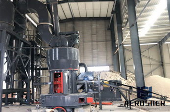
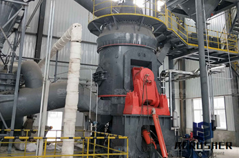
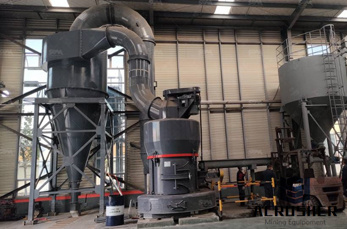
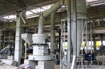
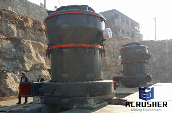
Cement manufacturing: components of a cement plant. This page and the linked pages below summarize the cement manufacturing process from the perspective of the individual components of a cement plant the kiln, the cement mill etc.. For information on materials, including reactions in the kiln, see the '' Clinker '' pages.
iii DESCRIPTION OF REVISION This revision, which supersedes the Goddard Space Flight Center (GSFC) Standard X673641E, Engineering Drawing Standards Manual, is intended to update and reflect the latest formats and standards adopted by GSFC.
As built PFD/ P ID Drawings using Smart Plant P ID. • Survey, collection of input data from field installations, input verification creation of 200 Nos. PIDs and 40 Nos. PFDs, A2 size drawing and mark the site verified data on the drawings. • The conversion .
A piping and instrumentation diagram (PID) is a detailed diagram in the process industry which shows the piping and process equipment together with the instrumentation and control devices.. Superordinate to the PID is the process flow diagram (PFD) which indicates the more general flow of plant processes and the relationship between major equipment of a plant facility.
Aug 17, 1971· materials are produced in portland cement manufacturing plants. A diagram of the process, which encompasses production of both portland and masonry cement, is shown in Figure As shown in the figure, the process can be divided into .
A concrete plant, also known as a batch plant or batching plant or a concrete batching plant, is equipment that combines various ingredients to form of these inputs include water, air, admixtures, sand, aggregate (rocks, gravel, etc.), fly ash, silica fume, slag, and concrete plant can have a variety of parts and accessories, including: mixers (either tilt drum or ...
The Definition of PID PID, short for piping and instrumentation diagram, is a detailed diagram that represents the technical realization of a process by means of graphical symbols, such as the service lines, instruments, controls, valves, and equipment.
P iping and instrumentation diagrams represent the important components of a physical process flow. Lucidchart is a webbased application for building PIDs and other technical diagrams. Try the simple draganddrop interface and online sharing options. You can even access your diagram from any device or location.
Below are some common PID symbols used with the instrument abbreviations discussed above for developing PID drawings . Tag Numbers on PID Symbols. Numbers on the PID symbols in instrumentation diagrams represent instrument tag numbers. Often these numbers are associated with a particular control loop (, Temperature indicator and ...

A Process and Instrument Drawing (PID) includes more details than a PFD. It includes major and minor flows, control loops and instrumentation. PID is sometimes referred to as a Piping and Instrumentation Drawing. These diagrams are also called flowsheets.
Electrical Diagram; PID; Others. Business Diagram; Form; Business; Download; Support; Promotion; Contact Sales. ... Plant PID. 10350. 118. Electrical Diagram. 9961. 97. Water Boiling Process PID. 9657. 122. Wastewater Treatment PID. ... Share your great PID with us in our sharing community! All PID templates are available to download, edit ...
Basic Rules for Creating PID. Pipe lines are represented by single lines in PID.; Instrumentation signals and connection lines are represented by different types of dashed lines. Industry standards for the PID are ISA and ISO 146176.; PID should be readable either from left to right or from right to left of the drawing.
of complexity to the treatment plant operation. 2. Small RO Plants Small RO plants vary from the needs of a single up to 400 000 gal day1 (gpd) (1 818 400 l day1) and usually consist of a single RO unit. Plants of this size are generally assembled on a .
WhatsApp)